The control board in the toy is very simple, having no integrated circuits. It receives the control signal in the 27MHz band and translates it into bi-directional control of the two DC motors — one main drive motor and one turn motor.
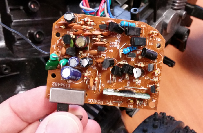
The underside of the board has plenty of opportunities to stick a multimeter in and figure out what’s going on.
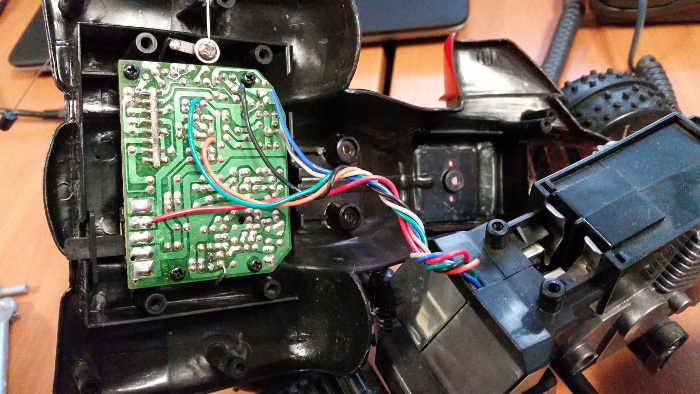
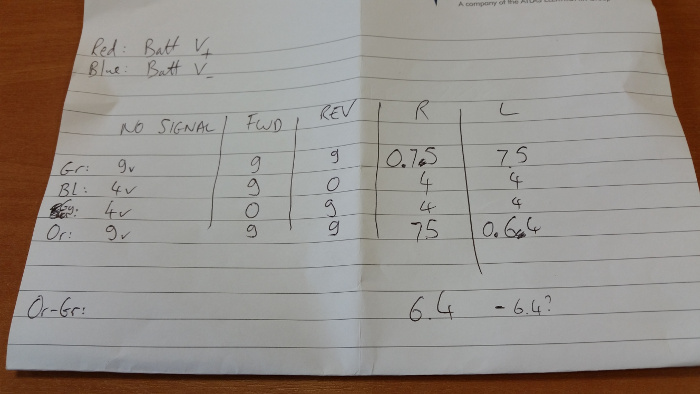
The red and blue wires only connect to the battery pack, providing the control board with +9v and 0v respectively.
The other four wires connect to the motors, two to each. Black and grey control the main drive motor, while green and orange control the turn motor. Both operate using a simple differential voltage to produce the bi-directional rotation, although it looks like the turn motor is fed a slightly lower voltage than the drive motor.
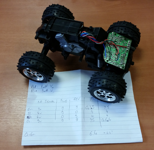
This is where the All-Terrain Pi is now: a stripped down vehicle with electronics exposed, and a complete set of voltages recorded that will allow us to remove the control board and replace it with our own electronics.
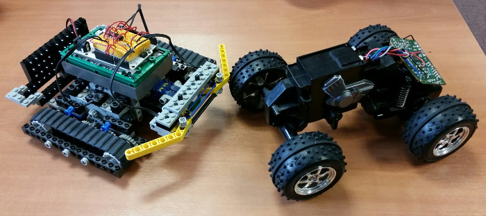
Here’s a bonus shot of the ATP hanging out with the Lego Turtle!
Add a Comment