Naturally, the first step to modifying this thing is to take it apart and figure out what’s in there. So without further ado, let’s gut some fish!
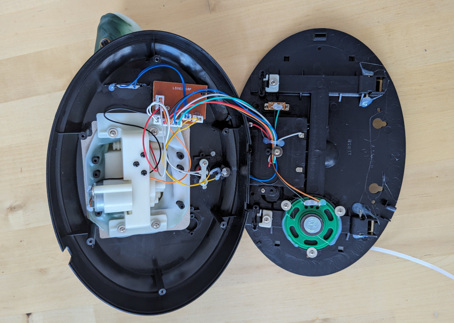
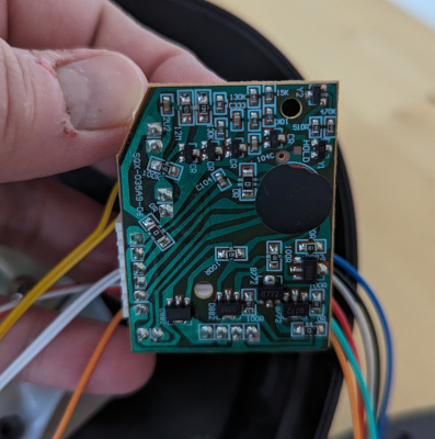
The back is easily taken off after removing six cross-head screws. Inside, it’s… surprisingly nice! I hadn’t read up too much on Billy Bass hacking at this point in the project, so I was kind of expecting wires soldered onto a board of the cheapest possible components—it turns out that was what the original Billy Bass was like, but the newer versions such as this 15th Anniversary edition have a nice neat connectorised board.
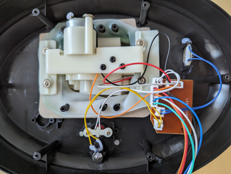
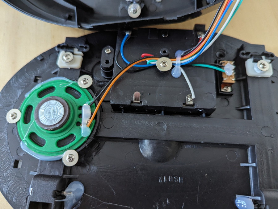
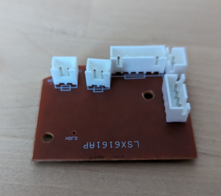
Here’s the close-ups of the two halves:
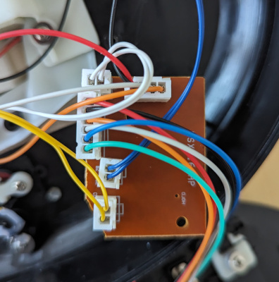
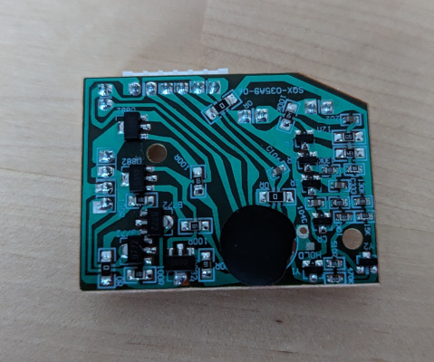
Some further close-ups of the PCB—enhance!
A quick trace through of the wires reveals this as the wiring diagram for the Big Mouth Billy Bass 15th Anniversary edition:
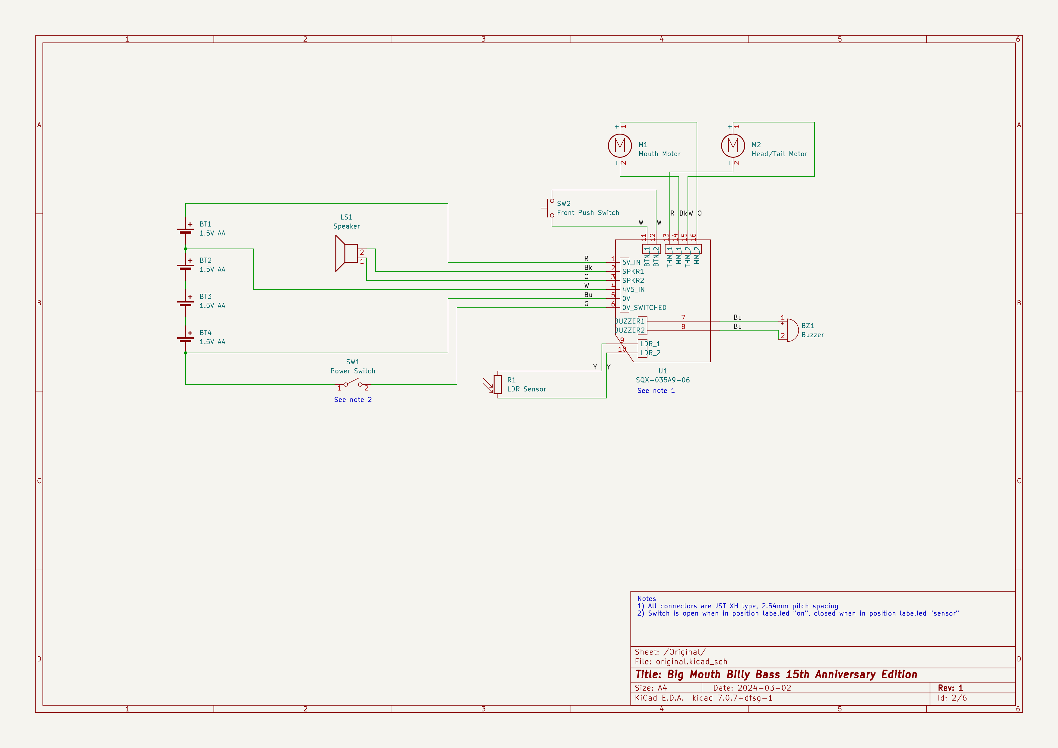
As for the schematic for the PCB itself, a full schematic is stymied by covering the main chip in epoxy, although James Bulpin has helpfully provided a partial schematic for the motor driver section of the board, as his project retains this section of the PCB to drive the motors from lower-power Arduino analogue outputs.
Since the internals of the fish are neatly connectorised in this version, I decided to retain this for my build so that it could be modified without cutting any wires, and could be reverted back to its former “glory” if desired. With that in mind, I purchased some JST XH sockets for my prototyping breadboard. In the part 3, I’ll get that connected up and start controlling the fish’s motors, but first we need to try out the ESP32.
Add a Comment