So far, the prototyping of the electronics has all used solderless breadboard. While convenient, it’s also quite fragile—in particular the legs of the JST XH connectors are short and prone to falling out. And as previously discussed, there’s no way the chunky breadboard and mess of wiring is ever going to fit back inside the fish enclosure.
We need to step things up a notch.
Not Quite Perf-ect
My next step was to replace the solderless breadboard with soldered perfboard. This made the whole thing much less fragile, although unfortunately not quite compact enough to fit it back inside the fish enclosure.
I imposed the design constraints that I wanted all the connectors at one end of the board, plus easy access to the SD card and USB socket.
I used Veroroute to design the perfboard layout, and after a while of moving components around, I settled on the following to meet the requirements:
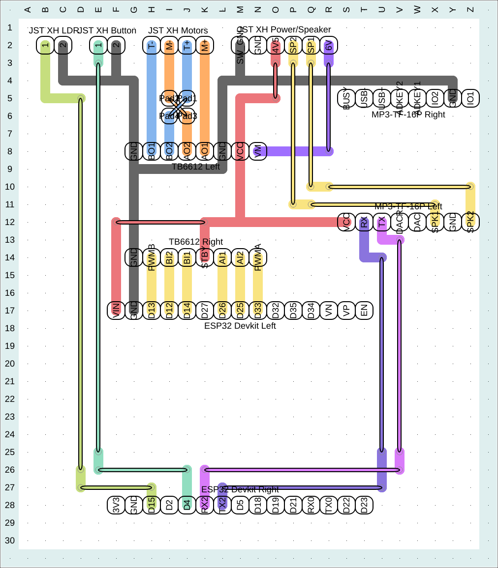
The design was made to fit within the bounds of a common 30x26 hole perfboard sheet. JST connectors are located at the top in a neat row; the micro-USB socket is to the left and the SD card ejects to the right-hand side.
In order to neatly line up the motor driver board with the ESP32, I made a minor change to the schematic. To allow space for the TB6612’s “standby” pin, I temporarily moved control of the mouth motor from pins D27/D26/D25 to D26/D25/D33, and bumped the LDR from D33 to D15. (Note that this change was reverted in the PCB version, below, which is back to the original pin layout.)
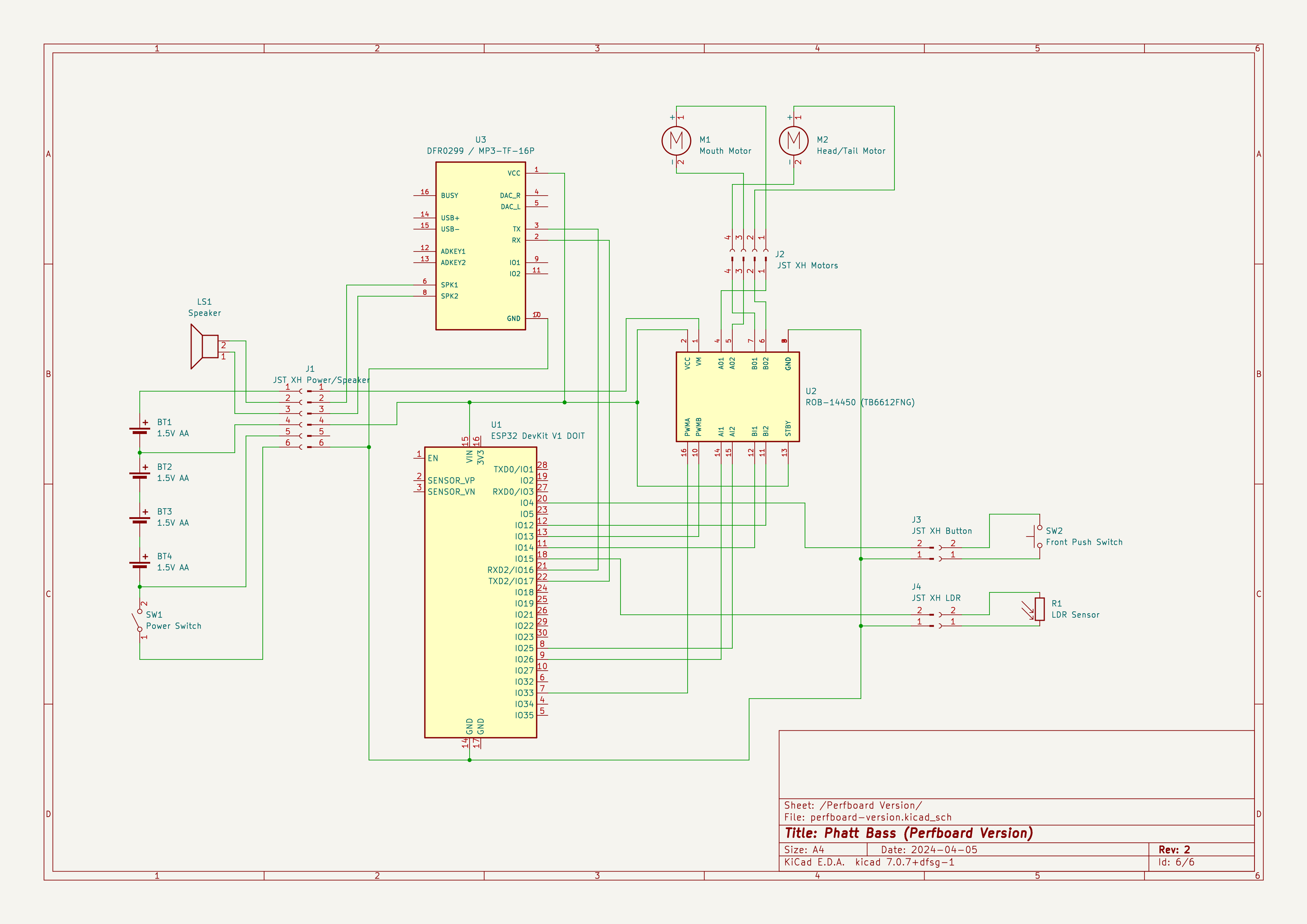
The schematic for the perfboard is as follows:
This One Goes to 11
That’s all well and good—the unit it a lot less fragile now, but my rubbish perfboard solder tracks are now on show to the world, and there’s still an ugly board hanging out of the back of the fish, because it’s still too big to fit back inside.
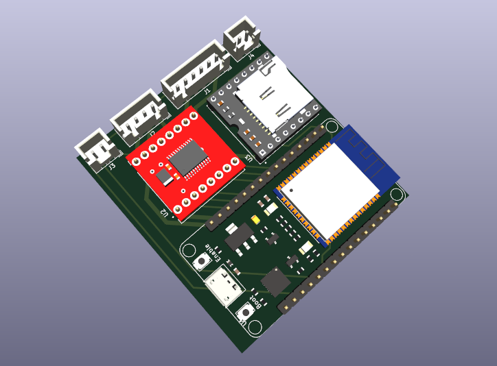
To take it to the next level, it’s time for a step I never thought this of all projects would involve: PCB design.
I wanted to keep the same components and rough board layout, while minimising the overall footprint as much as possible. A single board with all key components on it is beyond my skill level, but I can at least design a motherboard that fits the three daughter boards we already use.
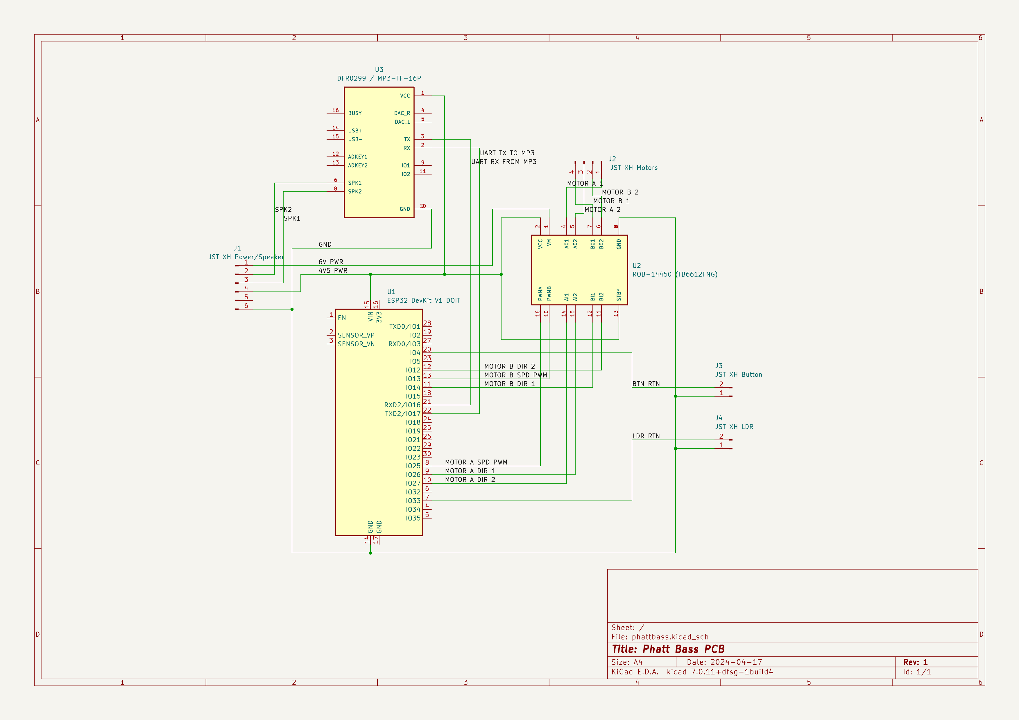
I began with a new schematic which only contained the board components rather than showing the external fish electronics, and added naming and classifying of the nets. At this stage I also reverted to the original pin allocations on the ESP32 from the solderless breadboard stage, as I had no need to make concessions for the perfboard.
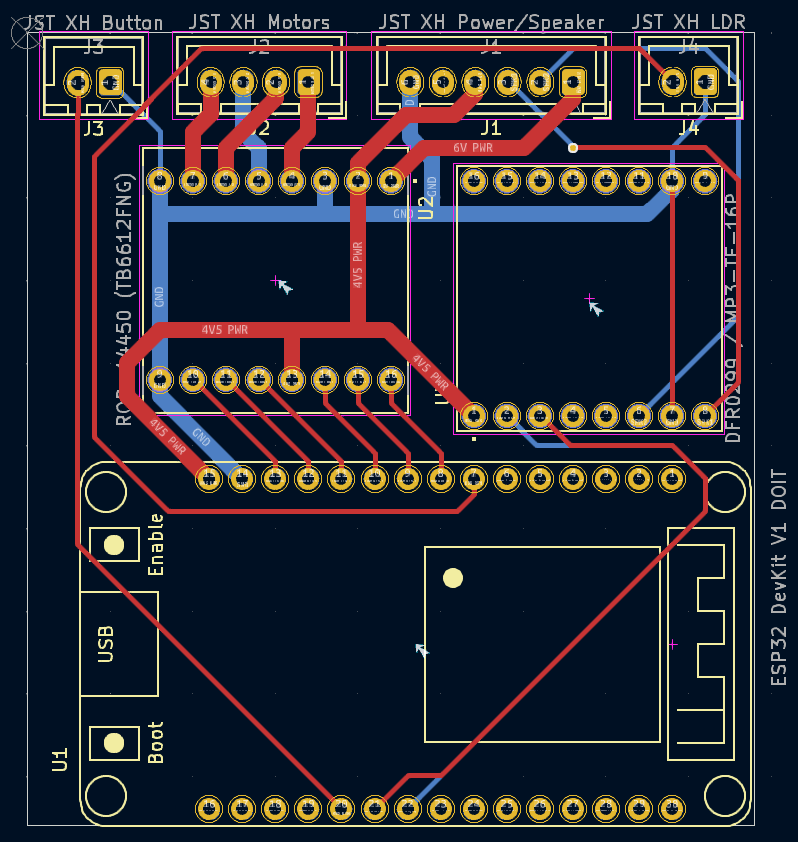
I then progressed to the PCB design view in Kicad, laying out the board to be as compact as possible given the components required. I couldn’t quite manage zero vias, but in the end needed one. So close!
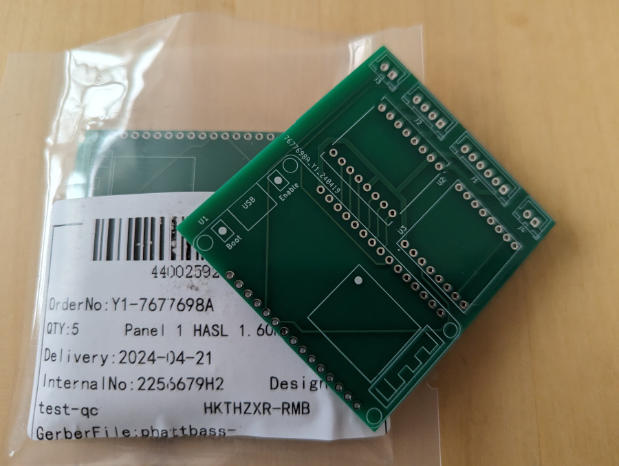
You can download the Gerber files here.
I had the board manufactured by JLC PCB for the princely sum of two dollars. If you’re following this guide, they can make one for you too—and if you’re in the UK, MOQ was 5 so I have four spare boards, and will send you one for free if you like.
All that’s left on the hardware side was to fit the parts and solder it up.
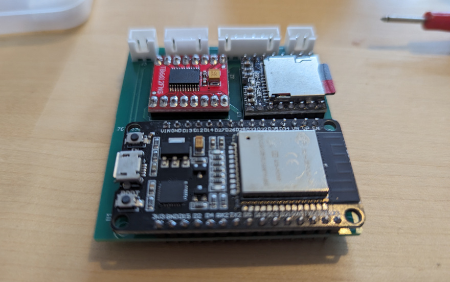
My soldering skills are trash so I’m not sure if I found it a challenge to solder just because of that, or because the pads were quite small. It was also a minor challenge to get the ESP32 Devkit lined up well enough that the pins went in. If I were to remake the project I might consider increasing the hole and pad sizes around the legs of the main components.
The PCB only just fits in the enclosure, at a slightly dodgy angle, and with the connector/component side towards the front of the fish. My soldering is therefore unfortunately on show during my a last check that the dimensions are right.
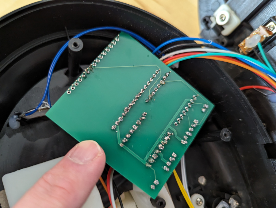
But at long last, we can finally put the fish back together. No more fragile breadboard hanging out of the back!
MC Fish
With the electronics fully enclosed, we have added a couple of new limitations.
Firstly, the ESP32 Devkit’s on-board LED was used to indicate the starting mode and which track number was selected. That’s now no longer visible.
I did think about replacing the rarely-used LDR on the front of the unit with an LED, but in the end I decided I’d rather keep the functionality. Instead, I took advantage of the MP3 player’s ability to manage multiple folders. In one, I put the music MP3s themselves; in the other I put a set of “announcer” voices that play at startup (to indicate the mode) and on a long button press (to indicate the track). I generated these using the gtts library for Python, which provides a command-line interface to Google’s text-to-speech service, like this:
gtts-cli "Track 1. Fat Bass." -o 001.mp3
The code was then updated to use this approach instead of the LED flash.
When using folders, rather than playing “global” MP3 files, the files can no longer have descriptive names and must be named specifically XX/YYY.mp3 where XX is a zero-padded folder number, and YYY is a zero-padded track number. So for example, I have 01/001.mp3 as the Phatt Bass song, and 02/001.mp3 as the announcer voice that says “Track 1”. I also added a special announcer track as 02/099.mp3 to say “sensor mode enabled” at startup if in that mode.
Click here to download the contents of the SD card that go with the code.
The other limitation is that if I want to reprogram the device or add new songs, I’d need access to the ESP32 Devkit micro-USB socket and SD card, which requires taking the unit apart. As a quick and dirty solution, since we already have a hole drilled in the back, I chose to fit a USB cable and a microSD card “extender” so that both are accessible from the outside. This does the job although it’s hardly neat; in future I may improve this to mount the SD card extender internally but accessible through a dedicated slot on the outside, and fit a bulkhead mounted microUSB socket. I can’t un-drill my hole, but it would provide a neater solution for anyone following the guide in future.
And that’s about it! Nothing left to do but think of more silly things for a Billy Bass to sing and lip-sync to.
The Future is Fishy
A future project re-using the fish may take advantage of the ESP32’s Bluetooth receiver and replace the MP3 player with an audio amplifier. With some code to automatically detect and react to audio, rather than our current scripted lip-syncing, I may repurpose the Billy Bass as a Google Assistant speaker or car sat-nav.
Add a Comment