With the ESP32 development board set up and programmable, the next job was to gain control over the fish’s motors, and power the board along the way.
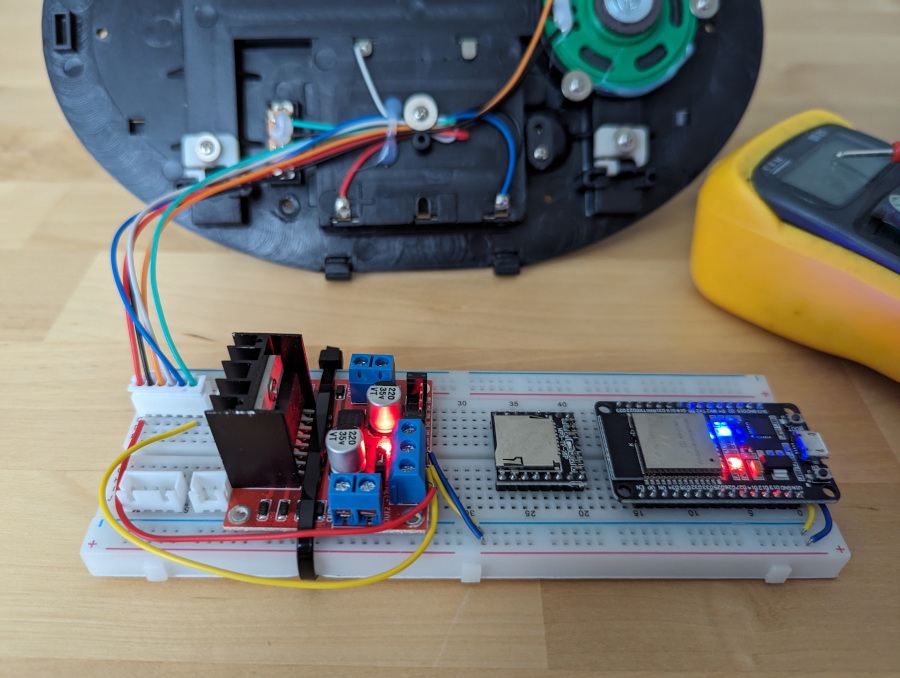
I initially chose an L298N board for this, attached it temporarily to the breadboard, then started to wire up.
Content Warning: I used whatever bits of single-core wire I had lying around for this stage of the project. If you are sensitive to poor wiring colour choices, you may wish to look away now.
Power Up
One key advantage to the L298N is that it has a 5V output which we can conveniently use to power the board, stepping down the 6V that comes from the fish’s 4x 1.5V batteries.
Now came the question of where to wire from. In the original circuitry, some part of the PCB stays powered the whole time, and the switch options are marked “on” or “sensor”—there is no “off”.
While the ESP32 is a low power component compared to having a full computer in here, its power draw is still going to flatten the batteries after a while. Therefore, during the early stages of development, I wanted to repurpose this as a proper on/off switch so that I could easily turn the ESP32 & L298N off when not in use, and prevent battery drain.
I therefore took 6V from the red wire on the 6-pin header, and the switched 0V from the green wire. These were wired into the L298N’s input power pins, and 5V & 0V then taken off to the breadboard power rails. The ESP32 could then be powered from the fish batteries.
Motor Control
I largely followed this excellent tutorial to use the ESP32 to drive the motors. In essence, the way the L298N works is as follows:
- Each motor has two logic level inputs for forward and reverse
- Each motor also has an “enable” pin that comes jumpered to a neighbouring 5V pin
- The jumper can be removed and a PWM input applied in order to control the motor speed.
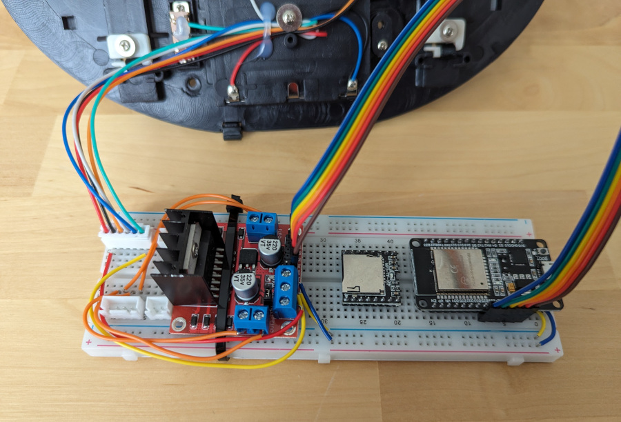
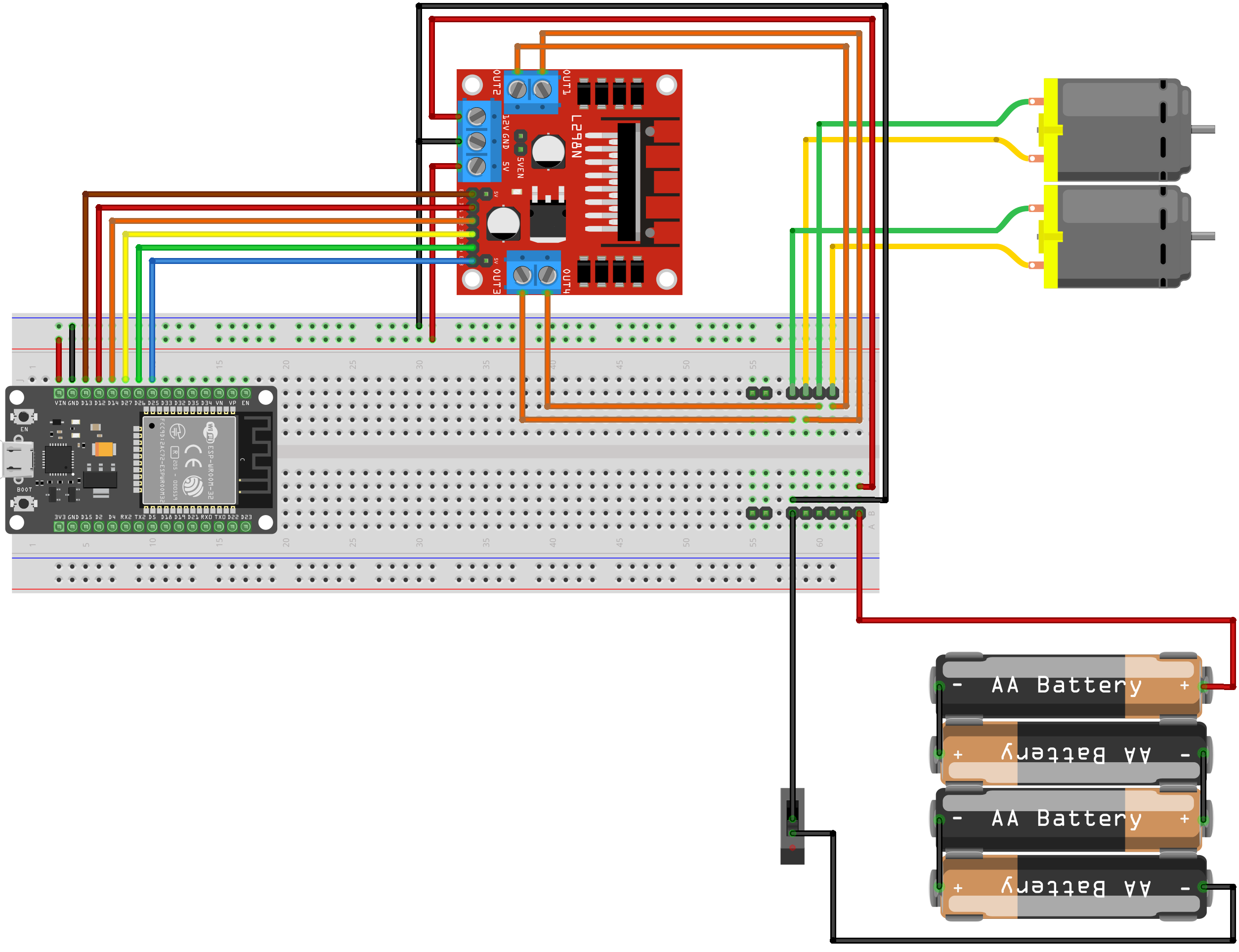
All ESP32 output pins can be used for PWM, so I wired a neat row of pins using ribbon cable as follows:
- D13 to Enable A (PWM) (brown)
- D12 to IN1 (Motor A forward) (red)
- D14 to IN2 (Motor A reverse) (orange)
- D27 to IN3 (Motor B forward) (yellow)
- D26 to IN4 (Motor B reverse) (green)
- D25 to Enable B (PWM) (blue)
Note that I have a "JZK" branded development board. This is "relatively" standard, and similar to for example the DOIT and other 30-pin ESP32 devkits. However pin-outs are not 100% consistent across boards so if you're following along with this guide at home, check the layout of your board.
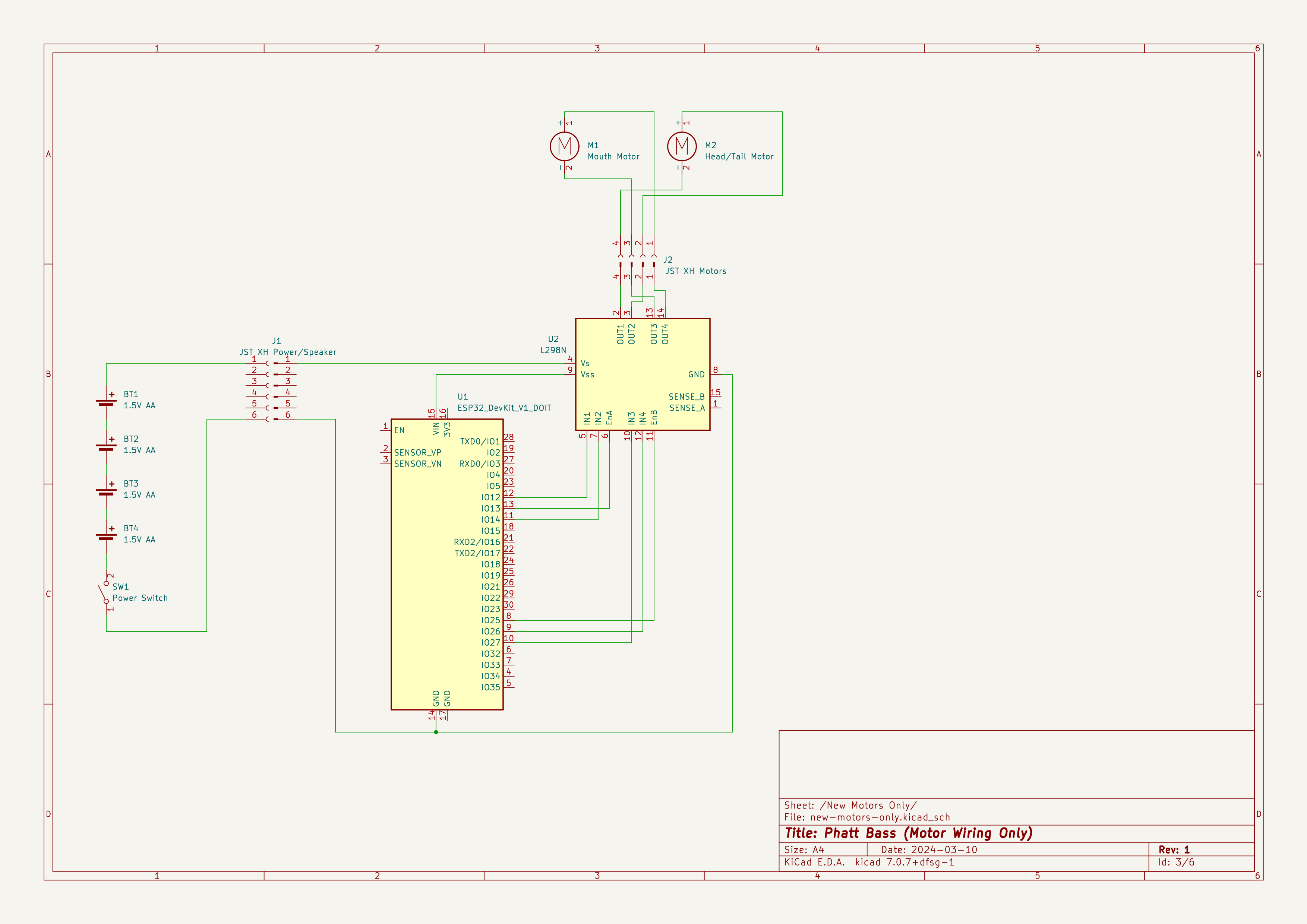
I then wired the outputs of the L298N to the JST socket to which the motors will be attached. The schematic now looked like this:
And the board like this:
While in the solderless breadboard stage of prototyping on this project, I will also include Fritzing “layout” diagrams to aid understanding of what’s going on:
Hacking Code
The next step was to write some simple code to demonstrate motor movements. The following code operates each motor in sequence:
// Motor control pins
#define HEADTAIL_MOTOR_PIN_1 12
#define HEADTAIL_MOTOR_PIN_2 14
#define HEADTAIL_MOTOR_PWM_PIN 13
#define MOUTH_MOTOR_PIN_1 27
#define MOUTH_MOTOR_PIN_2 26
#define MOUTH_MOTOR_PWM_PIN 25

// LED pin for debug
#define LED_PIN 2

// Motor PWM settings
#define PWM_FREQUENCY 1000
#define PWM_RESOLUTION 8
#define HEADTAIL_MOTOR_PWM_CHANNEL 0
#define MOUTH_MOTOR_PWM_CHANNEL 1
#define HEADTAIL_MOTOR_PWM_DUTY_CYCLE 255 // Proxy for motor speed, up to 2^resolution
#define MOUTH_MOTOR_PWM_DUTY_CYCLE 255    // Proxy for motor speed, up to 2^resolution

void setup() {
  // Set up pins
  pinMode(HEADTAIL_MOTOR_PIN_1, OUTPUT);
  pinMode(HEADTAIL_MOTOR_PIN_2, OUTPUT);
  pinMode(HEADTAIL_MOTOR_PWM_PIN, OUTPUT);
  pinMode(MOUTH_MOTOR_PIN_1, OUTPUT);
  pinMode(MOUTH_MOTOR_PIN_2, OUTPUT);
  pinMode(MOUTH_MOTOR_PWM_PIN, OUTPUT);
  pinMode(LED_PIN, OUTPUT);

  // Set up PWM
  ledcSetup(HEADTAIL_MOTOR_PWM_CHANNEL, PWM_FREQUENCY, PWM_RESOLUTION);
  ledcSetup(MOUTH_MOTOR_PWM_CHANNEL, PWM_FREQUENCY, PWM_RESOLUTION);
  ledcAttachPin(HEADTAIL_MOTOR_PWM_PIN, HEADTAIL_MOTOR_PWM_CHANNEL);
  ledcAttachPin(MOUTH_MOTOR_PWM_PIN, MOUTH_MOTOR_PWM_CHANNEL);
  ledcWrite(HEADTAIL_MOTOR_PWM_CHANNEL, HEADTAIL_MOTOR_PWM_DUTY_CYCLE);
  ledcWrite(MOUTH_MOTOR_PWM_CHANNEL, MOUTH_MOTOR_PWM_DUTY_CYCLE);
}

void loop() {
  // Head forward
  digitalWrite(HEADTAIL_MOTOR_PIN_1, LOW);
  digitalWrite(HEADTAIL_MOTOR_PIN_2, HIGH);
  digitalWrite(LED_PIN, HIGH);
  delay(1000);

  // Tail forward
  digitalWrite(HEADTAIL_MOTOR_PIN_1, HIGH);
  digitalWrite(HEADTAIL_MOTOR_PIN_2, LOW);
  digitalWrite(LED_PIN, LOW);
  delay(1000);

  // Stop
  digitalWrite(HEADTAIL_MOTOR_PIN_1, LOW);
  digitalWrite(HEADTAIL_MOTOR_PIN_2, LOW);
  delay(500);

  // Mouth open
  digitalWrite(MOUTH_MOTOR_PIN_1, LOW);
  digitalWrite(MOUTH_MOTOR_PIN_2, HIGH);
  digitalWrite(LED_PIN, HIGH);
  delay(1000);

  // Mouth close
  digitalWrite(MOUTH_MOTOR_PIN_1, HIGH);
  digitalWrite(MOUTH_MOTOR_PIN_2, LOW);
  digitalWrite(LED_PIN, LOW);
  delay(1000);

  // Stop
  digitalWrite(MOUTH_MOTOR_PIN_1, LOW);
  digitalWrite(MOUTH_MOTOR_PIN_2, LOW);
  delay(500);
}
You can see it in action below!
Add a Comment