On a previous page, I mentioned the odd nature of the Billy Bass power switch: its two options are labelled “on” and “sensor”. What these options actually seem to mean is that either way, a low-power part of the board is powered up, waiting for an input. If the switch is in the “on” position, it’s pushing the red button on the front that triggers the fish into action. If it’s in the “sensor” position, a light-dependent resistor in the front of the unit is used to detect “motion”, and this signal then triggers the fish.
In the final set of electronics mods, I’d like to recreate both original behaviours. However, like I said in that earlier page, an ESP32 is a relatively power-hungry thing, and I’d prefer the switch to be used to fully isolate the electronics from the battery in this case.
I’ve therefore got three jobs left in this area:
- Get the ESP32 responding to the button press
- Get the ESP32 responding to the LDR
- Provide a choice between modes.
The Button Press
First, the easy bit. We don’t even need an external pull-up resistor for this, because the ESP32 dev boards have their own internal ones, which can be enabled in software! It’s like living in the future. All we need to do is wire the button so that one end connects to ground, and the other end to one of the ESP32’s internal pull-up pins, in my case pin 4.
The following test program shows the state of the pin using the Arduino IDE’s serial console, which gives a 1 when the button is unpushed (circuit open, therefore pulled up) and a 0 when the button is pushed.
#define BUTTON_PIN 4

void setup() {
  Serial.begin(9600);
  pinMode(BUTTON_PIN, INPUT_PULLUP);
}

void loop() {
  int buttonState = digitalRead(BUTTON_PIN);
  Serial.println(buttonState);
}
The LDR
The LDR input is a little more tricky, but only a little. To start with, I measured the resistance across it in various light conditions:
| Condition | Measured Resistance |
|---|---|
| Blocked, no light | >2MΩ |
| Indoors, room lights off | 180Ω |
| Indoors, room lights on | 110Ω |
| Phone torch 3cm away | 2Ω |
Thankfully, this range seems pretty compatible with the ESP32’s pull-up resistors, which we can also use on analog input pins! So once again we have a very simple circuit, where we wire one side of the LDR to ground, and the other side to an input pin, in my case pin 33.
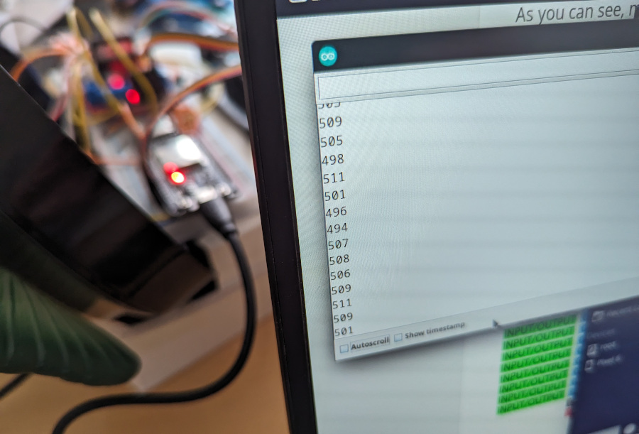
The following test program then shows the light level, again in a slightly inverted way due to the use of a pull-up rather than pull-down resistor:
#define LDR_PIN 33

void setup() {
  Serial.begin(9600);
  pinMode(LDR_PIN, INPUT_PULLUP);
}

void loop() {
  int lightLevel = analogRead(LDR_PIN);
  Serial.println(lightLevel);
}
The measured levels are as follows:
| Condition | Approx Measured Level |
|---|---|
| Blocked, no light | 2500 |
| Indoors, room lights off | 400 |
| Indoors, room lights on | 200 |
| Phone torch 3cm away | 0 |
The Choice
In order to provide the user with a choice of either using sensor mode or not, we need more than just the one power switch. I’ve chosen to implement the logic in the following way:
- If the front button is pushed down at the point the code starts running, we will go into “sensor” mode. It waits for the button to be un-pushed, then waits 5 seconds. Now, it watches for a rapid drop in light level that suggests someone is moving nearby, and uses that to trigger the song.
- If the front button is not pushed at the point the code starts running, we will go into “on” mode, where the button must be pushed to trigger the song.
The logic is as follows, shown as a test program to help get the right levels:
#define BUTTON_PIN 4
#define LDR_PIN 33

bool sensorMode = false;
double lastSensorLightLevel = 0;

void setup() {
  Serial.begin(9600);
  pinMode(BUTTON_PIN, INPUT_PULLUP);
  pinMode(LDR_PIN, INPUT_PULLUP);

  // For debug, give you chance to open serial console and hold button
  // if desired.
  delay(10000);

  if (isButtonPushed()) {
    // Button held in on startup, so going into sensor mode.
    // Wait for button to be unpushed, then wait 5 seconds for the user to move away
    Serial.println("Sensor mode");
    sensorMode = true;
    while (isButtonPushed()) {
    }
    delay(5000);
  } else {
    Serial.println("Button mode");
  }
}

void loop() {
  // Wait for a trigger condition, either a change in light level or
  // a button push depending on our mode.
  if (sensorMode) {
    double lightLevel = getLightLevel();
    Serial.println(lastSensorLightLevel - lightLevel);
    if (lightLevel < lastSensorLightLevel - 0.04 || lightLevel > lastSensorLightLevel + 0.04) {
      trigger();
    }
    lastSensorLightLevel = lightLevel;
    delay(200);

  } else if (isButtonPushed()) {
    trigger();
  }
}

// Return true if button is pushed
boolean isButtonPushed() {
  return digitalRead(BUTTON_PIN) == 0;
}

// Return a normalised light level 0-1
double getLightLevel() {
  int measuredLevel = analogRead(LDR_PIN);
  return constrain(1 - measuredLevel / 2500.0, 0.0, 1.0);
}

void trigger() {
  Serial.println("Trigger");
}
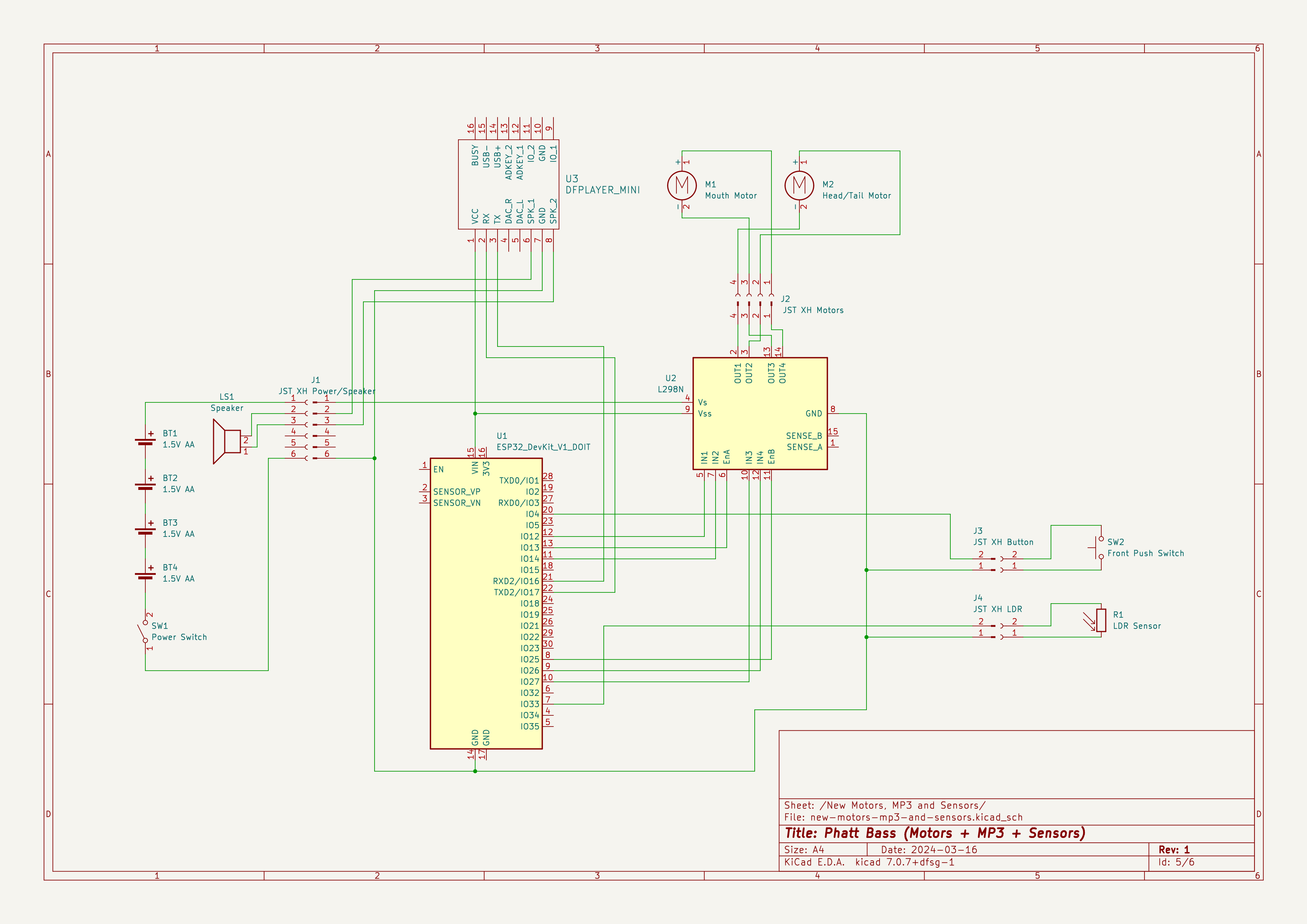
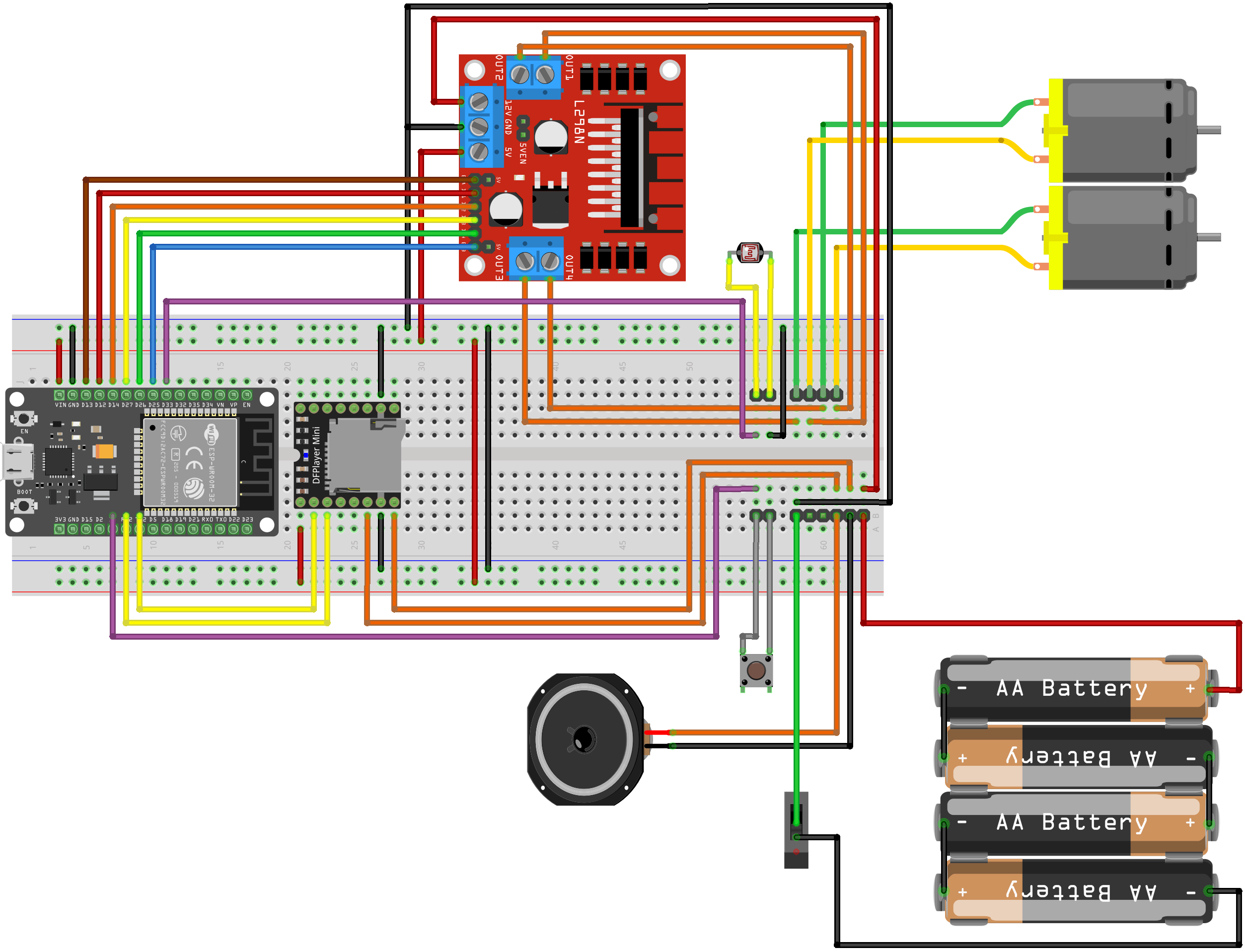
With the new components in place, the wiring looks like this:
Add a Comment